 Menu
Menu

 Log on
 Member registration
1. Introduction
Digital technology innovations are advancing rapidly worldwide toward the realization of an ultra-smart society, driving change in both electronic boards and the parts that are placed on them.
For example, watching videos and playing games via the internet is increasingly commonplace, and the volume of data being sent is increasing. High-functionality devices such as CPUs that are used in infrastructural communication equipment to process large amounts of data at high speed are becoming increasingly larger as their capacity increases. The move to EVs is being driven by concerns over environmental damage caused by fossil fuels, and so the connectors used in these vehicles are needing to be larger to be able to handle the large currents being passed through from the batteries and other components.
This article discusses the handling of large parts such as the aforementioned high-functionality devices and connectors, the challenges posed in placing these in the SMT process, and Fuji's solutions to these issues.
Issues for placing large parts
Due to complexities in part shapes and needing to work within the specifications of placement machines, the following kinds of issues can occur.
- Taking a long time to create vision processing data
- Difficulty in positioning leaded parts
- Unstable quality when needing to resort to manual insertion
The term "large odd-form parts" is now ubiquitous in the industry, and as the term suggests large parts tend to also come in complicated shapes with specific properties, and so the handling method differs for each part.
There are various solutions that Fuji is able to provide to meet contemporary issues.
2. Powerful support for creating complex vision processing data
If vision processing data is not properly set, misalignment and machine stoppage due to part recognition errors can occur. The number of new programs that need to be created is on the rise as the number of products to be produced increases due to the diversification of market needs. This data needs to be created in a short time while still being accurate.
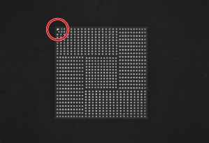
However, a high proportion of large parts have leads and bumps on the surface to be placed onto the panel. It is especially difficult to create vision processing data for parts on which bumps and leads are arranged in irregular patterns. It isn't unheard of for it to take ten minutes or more to create data for such parts.
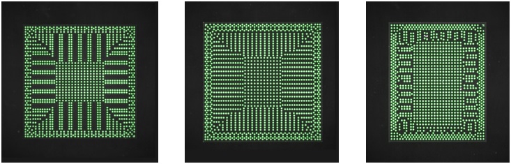
BGA with irregular bump pattern
Fuji makes it possible to create accurate vision processing data in a short time by using actual part images even for those parts that would generally take a long time to create data for.
2-1. Support software for creating vision processing data
Auto Shape Generator (ASG) uses AI technology to recognize and make settings for the leads and bumps, which usually take the most time to create vision processing data for, reducing the work required to create vision processing data to less than one-third *1.
The vision type used to set certain parameters during vision processing is selected automatically and testing whether imaging is possible with those parameters can be done offline. This reduces the frequency of imaging errors after production is started and keeps the lead time until ramping up to mass production short.
Parts that exceed 50 mm in one direction can be imaged by taking images in sections, making it possible to create accurate vision processing data in a short time just as can be done for smaller parts.
*1: Investigated at Fuji
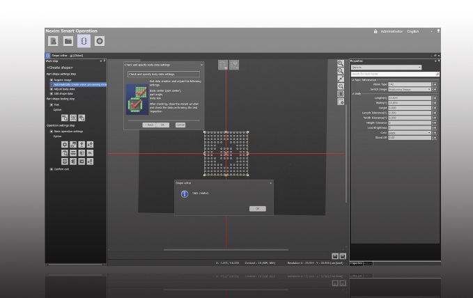
Vision processing data creation screen
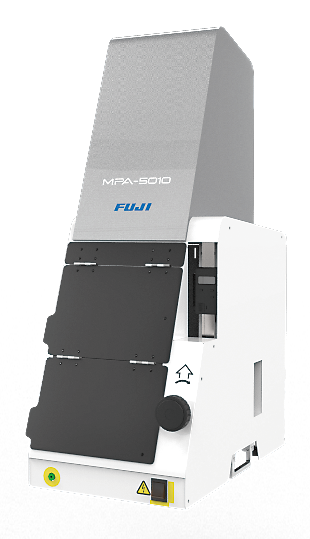
Camera stand dedicated for creating image data
Depending on the part, there may be large individual differences due to being from a different production lot. When parts are switched to a new lot, there are cases in which vision processing errors occur. In such cases, the images captured by the placement machine can be used to edit the data on the machine or on a computer in the line, and production can be restarted quickly. This means that stoppage time can be kept to a minimum.
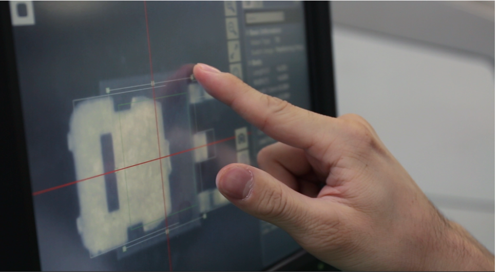
On-machine editing image on AIMEX III
3. Optimal solutions that cater to the different characteristics of individual parts
In order to perform production using large parts with high quality and efficiency, it is necessary to be able to cater to the different characteristics (shape, size, weight) of each part.
The examples here are a representative sample of the characteristics found with large parts, with solutions to suit these.
3-1. Precise positioning of parts with insertion leads
One of the issues that can make placing large parts difficult is the presence of insertion leads.
The insertion leads on these parts need to be inserted into through-holes on the panel, so it is the tips of these insertion leads, not the exterior of the part, that needs to be vision processed for accurate insertion. However, the tips of insertion leads come in a variety of shapes depending on the cutting and processing methods, making it difficult to accurately recognize the center of each lead.
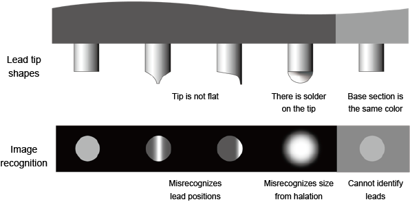
Shape of insertion leads and vision processing image
In order to eliminate misrecognition caused by variances in the shapes of lead tips, and prevent insertion errors, it is necessary to have a camera and lighting that enable accurate recognition of the tips of the insertion leads.
The sidelight camera uses an imaging method in which a laser is used to illuminate the insertion leads to make them easier to vision process. Using this method makes it possible to capture the center of the tip for any lead shape and allows for accurate positioning, preventing insertion defects.
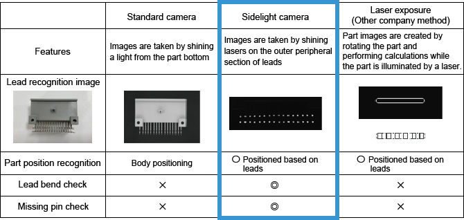
Differences in how leads look using different vision processing methods
3-2. Reliable insertion of parts with press-fit pins
Some large parts have pins attached that are used for securing the part in place so that it does not fall over or come out during transport, or raise up during secondary reflow. These parts can be placed securely using the insertion pressure control function, which applies a set amount of pressure during placement, pushing the pins into the holes in the panel.
Because the torque during pressure insertion is controlled, if the insertion pins are not inserted all the way in for some reason such as there is a foreign object that gets in the way, this will be detected as a defective insertion.
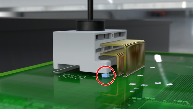
Insertion error detected
Applicable heads: DX-S1, H01, H01V, H02, H02F, OF
Maximum torque: 98N
There are other types of parts that require insertion pressure, but are prone to warping if they are pressed all at once, such as parts with low rigidity and shield cases. For these parts, it is possible to place the part down lightly before pushing it in at multiple points. This allows for perfect insertion without putting too much stress on the part.
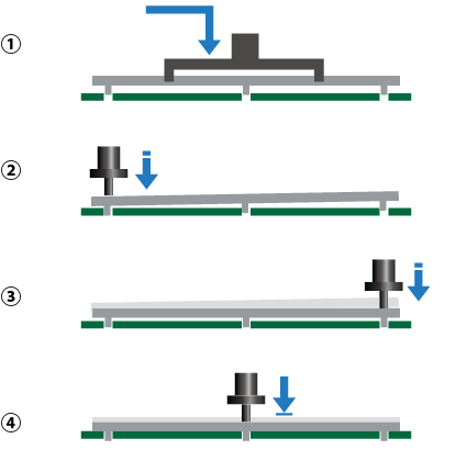
Part pushing function
3-3. Placement of tall parts
Most recent placement machines have become adept at placing parts that are large in the X and Y directions, but there are greater restrictions in the Z direction. Because of this, the maximum height that can be handled on a standard placement machine is approximately 25 mm. However, large connectors often exceed 30 mm in height, including the insertion leads, and thus must be inserted manually if they exceed the specifications of the equipment.
Fuji's placement machines support supply and placement of parts up to 38.1 mm (1.5 inches) in height. This expands the range of parts that can be assembled automatically on the SMT line, resolves issues that stem from manual insertion such as variations in quality and production time.
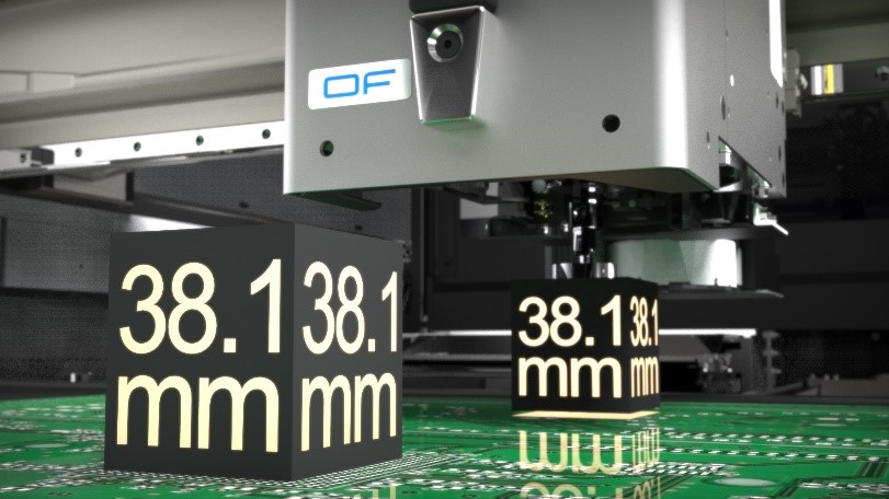
Support for placing parts up to 1.5 inches (38.1 mm)
3-4. Reliable handling of heavy parts
Large BGAs and large transformers that exceed 100 mm in one direction can weigh 200 g or more. The DX head, the head most suited to handling heavy parts in the Fuji head lineup, can handle parts up to 250 g. *2
However, heavy parts are prone to dropping during transport or rotation. Using custom nozzles that have been designed to pick up at the optimum position in regard to the shape and weight balance of the part is an effective measure to prevent parts from falling off after pickup.
*2: Proven value
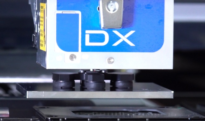
Placement of large 250 g BGA
3-5. Fine pitch placement of large parts
Usually a mechanical chuck is used to clamp the outside of the part when there is not enough flat surface on the top of the part for the nozzle to use for pickup. However there are parts, such as DIMM sockets *3, for which multiple parts are placed adjacent to one another. Mechanical chucks are not suited to handling these parts as interference between parts and the mechanical chuck will cause damage to the parts. If it is likely that this kind of interference might occur, a solution is to use a mechanical chuck that can clamp from the inside of parts.
*3: These are parts that serve as slots for the memory boards that are loaded onto a motherboard.
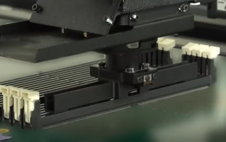
DIMM socket placement
Custom nozzles and custom mechanical chucks are able to be manufactured at Fuji locations across the globe, so that we are able to provide these tools in a short time.
3-6. Handling of parts that warp easily
Nozzles must be used to pick up thin parts that warp easily such as interposers, which are often used for boards in the latest smartphones. However, because interposers have bumps on any surface that might be used for pickup and thus is not flat, air leaks occur during pickup using nozzles, making it difficult to achieve stable handling.
There is a method in which nozzles with rubber pads are used, but rubber pads need to be replaced periodically, increasing the cost and maintenance work required.
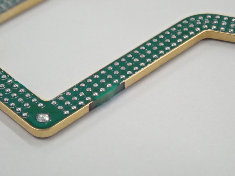
Interposer
For customers who place a lot of these types of parts that are prone to warping easily and are difficult to pick up using nozzles, we propose using our H01V head, which picks up parts using powerful vacuum pressure. With its more powerful vacuum pressure, H01V heads have four times the holding capacity of standard heads. By combining the H01V head with a custom nozzle that matches the part shape, secure pickup of parts that are prone to warpage and air leaks during pickup can be achieved, enabling high-speed placement and improving productivity without sacrificing quality.
Interposer placement
4. Supply solutions for large parts
Most large parts are supplied in trays. However, because each part is so large, there is a limit as to how many parts can be set in one tray. Because of this, the resupply frequency is high and we often hear of issues regarding machine stops caused by high rates of setting mistakes and delayed resupply.
4-1. Detecting part setting mistakes using image recognition
It is possible to detect part setting mistakes in the vision processing process after production is started. However, parts with symmetrical shapes or parts with the same shape but different specifications are difficult to identify only using vision processing at the placement machine, and if the person setting these parts to the machine does not notice before they are loaded, the wrong part may be placed.
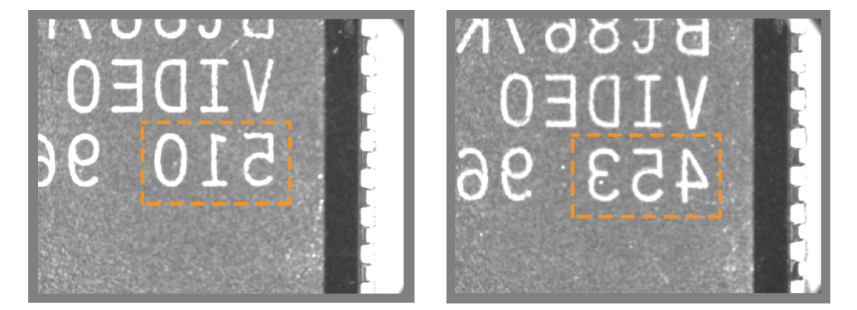
Part verification using Top View Recognition *4 takes images of the characteristics that are present on the tops of parts using the mark camera before a part is picked up. The part characteristics are verified against the part data so that defects that are caused by setting mistakes can be prevented. It is also possible to recognize markings printed on the parts, enabling lot management and the detection of setting mistakes in which parts are the same shape but have different specifications.
*4: Applicable machines: NXT-3, NXT-3c, AIMEX-3, AIMEX-3c
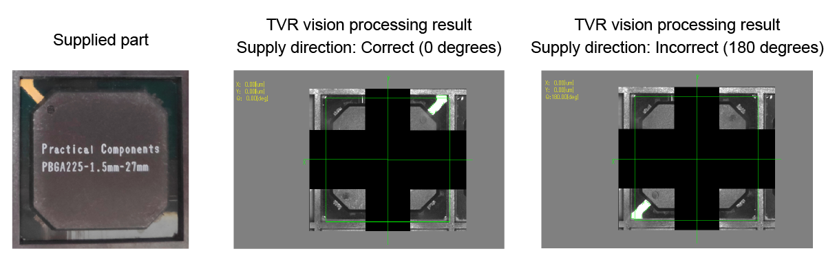
Angle check using the characteristics on the tops of parts - TVR part matching check
Low angle lighting unit
For markings that are difficult to recognize in images such as laser engraving, installing a low angle lighting unit *5 will make the markings show up clearly in images for recognition, so there is no need to be concerned about recognition errors.
*5: Applicable machines: AIMEX-3, AIMEX-3c
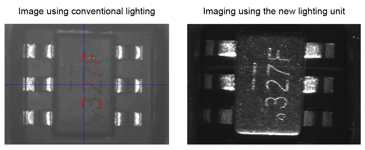
Low angle lighting unit
If there is a mark or characteristic on the bottom of a part, it is possible to check the direction of the part using the machine camera. The bottom mark check function detects when the wrong part has been set, preventing misplacements.
Angle check using the characteristics on the bottom of a part - Bottom mark check
4-2. Minimizing time lost when supplying tray parts
As mentioned above, large parts supplied in trays need to be resupplied more frequently, and if this resupply work is delayed, this will result in stops at the machine.
Fuji's tray units have two tray magazines, an upper magazine and a lower magazine. Through effective use of these two magazines, it is possible reduce the frequency of resupply, and keep supplying parts without stopping production.
Upper and lower magazine operation
4-3. Reducing the workload for supplying stick parts
Stacked stick feeders are recommended for large connectors that are supplied in sticks. Multiple sticks can be stacked on top of each other, and when the parts in one stick are used up, the empty stick is automatically ejected and production is continued using the next stick. This reduces the frequency of part resupply even for those parts used in large quantities, reducing operator workloads.
Stacked stick feeder
Large parts come in a variety of shapes and sizes, and by using functions and units that match with the characteristics of these parts it is possible to have automated production without compromising quality or productivity.
Fuji is able to provide further large part placement solutions using functions and units not discussed in the above.
Please contact us if you have any further questions about these or any other solutions.
 Contact